

Author: Marcello De Falco, Associate Professor, University UCBM – Rome (Italy)
1. Theme description
Carbon Capture and Storage (CCS) is the solution to “close the balance” between the carbon dioxide (CO2) emissions due to the combustion of fossil fuels (coal, oil and natural gas) for electricity generation and industrial processes and the CO2 natural capture, with the scope to mitigate the GreenHouse effect which would be a consequence of a CO2 content increase in the atmosphere and would have catastrophic effects on the ecosystems.
The interest on CCS technologies is increasing in the last years, mainly thanks to the targets imposed by the European Commissions to cut 20% of GreenHouse Gases emissions in EU by 2020: it will be impossible to reach the goal without implementing proper CCS solutions in the production plants.
In this framework, the EU policy has promoted the Emission Trading System (ETS) [1] scheme, known as the Carbon Tax, to drive the CO2 emissions reduction by introducing a tax on the emissions over an allowed level. The EU ETS system operates in the 28 EU countries plus Iceland, Liechtenstein and Norway and is focused on industries as the power and heat generation and the energy-intensive activities including oil refineries, steel works and production of iron, aluminum, metals, cement, lime, glass, ceramics, pulp, paper, cardboard, acids and bulk organic chemicals [2]. According to the EU ETS system, the companies receive allowances to emit tons of CO2 beyond the cap. If a company overcomes the cap, it has to buy other emissions allowances; on the other hand, companies that have implemented efficient technologies to reduce CO2 emissions can stay under the cap and sell the allowances to other less efficient companies, thus creating the ETS market. This mechanism creates an incentive to invest in technologies that cut CO2 emissions, as the CCS technology, and the ETS market is becoming huge, considering that in 2012 7.9 billions of allowance have been traded (total value = €56 billions).
2. Technologies
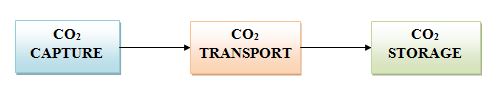
The CCS technology consists of three parts:
- the CO2 capture directly in the production plant;
- the CO2 transport to the storage site;
- the CO2 storage underground in depleted oil and gas fields or in deep saline aquifer formations.
The CO2 capture is surely the most interesting step from a technological point of view; the transport represents a no negligible cost (€5/tons of CO2 by onshore pipelines, decreasing at €3.7/tons if pipelines length is increased to 500 km; much more if the CO2 is transported by road tankers or ships); the storage is usually made in selected geological rock formation, typically located several kilometers below the earth’s surface.
2.1 CO2 capture technologies
Typically, CO2 is captured from the exhaust gas of a combustion process after the fuel combustor: this method is called post-combustion capture.
The most used process is the absorption process which uses MDEA (Methyl DiEthanol Amine) as the solvent. The exhaust gas containing carbon dioxide is fed to a packed column where a MDEA solvent is sent in counter-current configuration: CO2 is thus absorbed by the solvent and separated from the gas. Then, the solvent is stripped, releasing the CO2 stream, which has to be compressed and sent to the transportation step or directly to the storage, while the solvent is re-circulated to the absorption column (Figure 1).
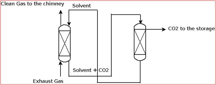
Fig. 1 – Absorption process for CO2 capture
Other post-combustion capture methods for separating CO2 are:
- high pressure membrane filtration [3] – a selective membrane allows the separation of CO2 from the other components of the exhaust gas by exploiting a pressure gradient driving force.
- Adsorption/desorption processes [4] – a sorption solid material, typically a mineral zeolite, is packed in a column where the exhaust gas is fed. CO2 is adsorbed in the solid pellets (operation stage) and separated from the clean gas, which is emitted to the atmosphere. Then, the solid is purified (regeneration stage) increasing the column temperature and thus desorbing the carbon dioxide. Such a cyclic operation uses two columns in parallel at least, one in the operation stage and the other in the regeneration stage.
- Cryogenic distillation [5] – the exhaust gas is cooled down to the CO2 sublimation temperature (-100 to -135°C), thus separating the solid CO2 from the light gases.
An alternative to the post-combustion capture processes is the pre-combustion CO2 capture technology.
By this process, the carbon dioxide is removed before the combustion of the fuel. Basically, the coal or the natural gas fuels are not directly burned but are converted to hydrogen and CO2 by steam reforming process (for natural gas) or by a gasification (for coal). Then, CO2 is separated in a similar way as in the post combustion process (typically by an absorption unit) and the hydrogen-rich gas is finally burned (Figure 2).
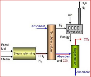
Fig. 2 – Pre-combustion CO2 capture thecnology [6]
Another process widely applied for CO2 capture is the oxy-fuel combustion. Before the fuel combustion, the oxygen required as combustive agent is separated from the N2. Then, the oxy-combustion produces a exhaust gas containing mainly H2O and CO2 (without N2) and the higher concentration of CO2 makes easier the post-combustion capture processes (Figure 3).
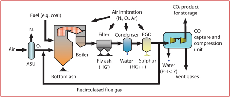
Fig. 3 – Oxy-fuel combustion process layout [7]
2.2 CO2 storage
Once the CO2 has been transported by pipelines, ships or road tankers, it is stored in geological formations located several kilometers under the earth’s surface. The injection is performed at temperatures and pressures such as the CO2 is in liquid or supercritical phase.
Suitable storage sites include:
- former gas and oil fields;
- deep saline formations, which represent a high potential carbon dioxide storage capacity, even if they are not well understood yet;
- depleting oil fields, where the injected carbon dioxide may increases the amount of oil recovered.
Once injected, the carbon dioxide moves up through the storage site until it reaches an impermeable layer of rock (known as the cap rock). The layer traps the carbon dioxide in the storage formation and such a mechanism is called structural storage.
Moreover, when the CO2 is moving up towards the cap rock, an amount of it is stored in the pores of the rocks: this mechanism is called residual storage.
Then, the stored carbon dioxide starts to be dissolved in the surrounding salty water, by a process known as dissolution storage, and, after long time, the CO2 binds chemically to the surrounding rock by a mechanism called mineral storage.
3. Innovations and Applications
All the principal companies operating in the power and heat generation and in the energy-intensive activities are devoting many efforts for finding competitive solutions to apply CCS technologies in their production plants.
ENI is studying geochemical models with the aim to assess the compatibility of its wells as CO2 storage site. Moreover, ENI is studying the CO2 pipelining for the transport and, in cooperation with ENEL, it performs a feasibility study on large-capacity integrated projects in Brindisi where carbon dioxide is produced and separated by MDEA unit in ENEL owned power stations, then piped to the storage site and injected into hydrocarbon fields or saline aquifers [8].
SHELL is conducting the Quest Carbon Capture and Storage Project [9], constructing a complete CCS plant at its Scotford oil sands Upgrader near Edmonton (Canada) on behalf of a joint venture and with the support of the Canadian and Alberta governments. The CCS unit will be able to store more than 1 million tons of CO2 per year, reducing the emissions of Scotford Upgrader by up to 35%. The total cost of the project is estimated at $1.35 billion, the CO2 will be transported by dedicated pipelines and stored in the Cambrian Basal Sands at a depth of 2.000 – 2.500 meters.
TOTAL participates in a number of international projects for the development of the different aspects of CCS, such as capture technologies, the behavior of CO2 during injection and storage, the long-term integrity of storage reservoirs and the risk analysis. Among them, the European programs DECARBit on the pre-combustion capture technology development and ReMove on monitoring and safety of reservoirs to be used for geological storage have to be cited [10].
Interesting studies are focused on Enhanced Hydrocarbon Recovery (EHR), including Enhanced Oil Recovery (EOR), Enhanced Gas Recovery (EGR) and Enhanced Coalbed Methane Recovery (ECBM): by injecting high-pressure CO2 in Oil&Gas fields it is possible to recover oil or gas that would be not extracted, leading to an economic revenue. A number of studies stated that the combining the the CCS and the EHR technologies would allow boosting the carbon capture applications [11]. A report of the Durham University [12] calculates that the CO2 captured through CCS and used for EOR in oil fields of North Sea could lead to a surplus of oil production of $200 billion.
Other interesting projects on storage technologies are:
- Sleipner CO2 Storage Project [13], by Statoil, ExxonMobil E&P Norway and Total E&P Norge, operative from 1996, with a pre-combustion capture technology based on absorption chemical solvent process (Amine), without CO2 transportation since the storage site is close to the production plant and able to store 0.9 million tons/year of CO2 in a sandstone at a depth approximately 800-1,100 metres.
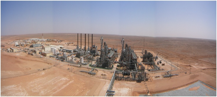
- In Salah CO2 Storage Project [14], a joint venture with BP, Sonatrach and Statoil, started from 2004 and able to store CO2 in a carboniferous sandstone at a depth of approximately 1.900 metres.

Fig. 4 – In Salah onshore industrial-scale CO2 storage site

- Weyburn-Midale Project in Canada, by which the CO2 is piped via an onshore pipeline for EOR in 2 carbonate fields.
__________