Thin Film Membrane Technology: Advances in Natural Gas Treatment
Author: Marcello De Falco, Associate Professor, University UCBM – Rome (Italy)
1. Theme description
Natural gas (NG) treatments are the processes needed to sweeten and purify the extracted NG before feeding it to the grid. Such processes are crucial to reach the gas purity targets and constitute a large fixed and operative costs for the NG production sector.
The main components to be removed in the NG purification process are the acid gases as carbon dioxide (CO2) and hydrogen sulphide (H2S) and, in many cases, the nitrogen (N2).
As reported in the following table, the contents of such components in the extracted NG stream can be high, leading to challenging and expensive separation processes.
| Groningen
(Netherlands) |
Laeq
(France) |
Uch
(Pakistan) |
Uthmaniyah
(Saudi Arabia) |
Ardjuna
(Indonesia) |
|
| CH4 | 81.3 | 69 | 27.3 | 55.5 | 65.7 |
| C2H6 | 2.9 | 3 | 0.7 | 18 | 8.5 |
| C3H8 | 0.4 | 0.9 | 0.3 | 9.8 | 14.5 |
| C4H10 | 0.1 | 0.5 | 0.3 | 4.5 | 5.1 |
| C5+ | 0.1 | 0.5 | – | 1.6 | 0.8 |
| N2 | 14.3 | 1.5 | 25.2 | 0.2 | 1.3 |
| H2S | – | 15.3 | – | 1.5 | – |
| CO2 | 0.9 | 9.3 | 46.2 | 8.9 | 4.1 |
Table 1 – Composition of natural gas reservoirs (%vol)[1]
Traditionally, the separation is carried out by means of:
1-Absorption processes, by which the components to be separated are absorbed on a liquid solvent in a packed column and then separated in the solvent regeneration step. The absorption of the component on the solvent can be chemical (chemical absorption) or physical (physical absorption). A wide applied absorption industrial process is the ammine separation (MDEA) unit for acid gases removal[2].
2- Adsorption processes, where selected components are adsorbed on the solid surface of specific particles. Then, increasing the solid bed temperature (Thermal Swing Adsorption – TSA) or reducing the pressure (Pressure Swing Adsorption – PSA), the gas is extracted and the solid is regenerated. The most applied adsorption process is the PSA, used to remove CO2 from natural gas streams by solid materials with a high affinity to carbon dioxide[3].
3- Cryogenic processes, known as low temperature distillation, which uses a very low temperature for purifying gas mixtures in the separation process exploiting the different gas components volatility. It is not applied for the acid gas removal from natural gas due to the low concentrations needed that makes the application of this technique not economical.But, a growing interest is given to separation processes using selective membranes thanks to their ease of operation, flexibility, smaller footprint and lower capital requirements.Basically, a membrane allows the transfer of certain components but not of the others, thus leading to a separation. A schematic layout is reported in Figure 1.
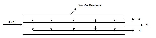
Figure 1 – Conceptual layout of a membrane-based separation process, with a membrane selective to component A.
Compared to the other natural gas separation techniques, the membrane process needs a lower energy requirement since it does not involve any phase transformation. Moreover, the process equipment is very simple with no moving parts, compact, relatively easy to operate and control, and also easy to scale-up and scale-down[4].In order to be applied in an industrial process, a selective membrane must have the following properties:
- high permeability, leading to a high flux of the separated component through the membrane thickness;
- high selectivity;
- high mechanical and thermal resistance at the separation unit operating conditions;
- the chemical resistance in the environment where the membrane is placed;
- low cost and long durability.
The permeability increases reducing the selective layer thickness, but at the same time, both the selectivity and the mechanical resistance are penalized with thin membranes. Therefore, the membrane design requires an accurate optimization. Usually, the applied membranes are composite and fabricated depositing a thin selective layer on a support able to assure the needed mechanical properties (refer to Figure 2).
 Figure 2 – Composite membrane architecture
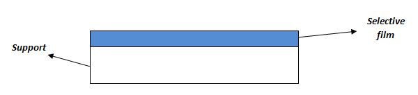 Figure 2 – Composite membrane architecture
In the following, some examples and applications of membrane applications for CO2, H2S and nitrogen removal from natural gas are reported.
2.Membrane application for CO2 removal
Carbon dioxide is the largest contaminant found in natural gas and, for this reason, a strong effort has been devoted to discover solutions to apply selective membranes in the CH4/CO2 separation process.Currently, the only commercial membranes applied for CO2 removal are polymeric, made by cellulose acetate, polyimides, polyamides, polysulfone, polycarbonates and polyetherimide[5]. The most widely used material is cellulose acetate as used in UOP’s membrane systems: the Separex membrane system has been applied in a number of large NG plants installed worldwide (refer to Figure 3)[6],[7]. Another widely applied commercial product is the cellulose tri-acetate (CTA) membrane developed by Cameron and called CYNARA[8]: such a membrane is applied in world’s largest CO2 membrane plant for natural gas clean-up (700 MMcf/d).
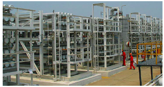
Figure 3 – Separex membrane skids installed at an EOR project in Latin America6.
Also Air Liquide has developed a membrane module for the purification of NG by removal of CO2, H2S and water steam[9]. The system is called MEDALTM and is able to reach the pipeline specification of 2 – 5% CO2 and 4 ppm H2S. Moreover, the membrane unit can be also used as a pre-treatment, removing the majority of CO2 and H2S, followed by a typical amine process to further remove carbon dioxide.Another product is proposed on the market by ProSep[10]: the membrane is fabricated in a flat sheet and the arranged into a spiral wound module, then inserted into steel pressure-containing tubes. Such a membrane module has been applied in a number of plants in U.S.A. and Colombia.
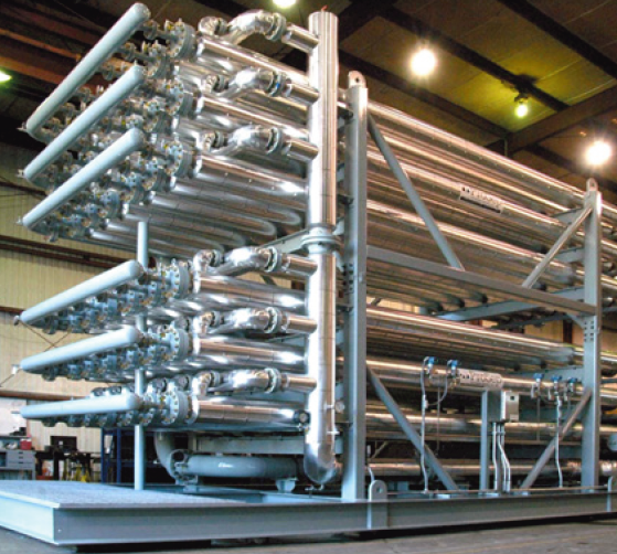
Figure 4 – ProSep membrane skid for CO2 removal installed in Texas.
The polymeric materials lead to a good separation performance but are poisoned by aromatics, organic liquid and water. For this reason, pre-treatment units have to be installed before the membrane separation device, leading to an increase of the costs and of the plant complexity.Some innovative membrane technologies have been developed and installed. As an example, the CO2 separation membrane provided by Membrane Technology & Research (MTR)[11] is a new polymeric membrane able to withstand the various components of the NG mixture, thus reducing the impacts of the pre-treatments.
3.Membrane application for H2S removal
On the contrary of the CO2 removal process by means of membranes, which now sees many industrial applications, the removal of H2S is still in a phase of pre-industrial development. The most interesting technologies are developed and tested by Membrane Technology & Research.MTR develops the SourSep™ systems bulk removal of H2S from pressurized sour gas[12]. The proposed architecture is based on a simple single stage process, able, thanks to a proper membrane installation, to assure a bulk removal of H2S (>75%). The permeate stream generated in very sour and can be re-injected in the extraction well or processed in a conventional Claus unit. The retentate stream has to be fed to other H2S removal unit (amine absorption or a scavenger process) to further reduce the sulfur content. Figure 4 shows a SourSep™ installation.
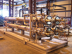
Figure 5 – SourSep™ MTR installation for the removal of H2S.
Another membrane application for H2S removal, always proposed by MTR, is for the achievement of the stringent H2S content target (< 40 ppm) if the NG is fed to an engine or a gas turbine. Such low composition is required to avoid the mechanical components corrosion and damage. A scheme of such a process, proposed by MTR, is illustrated in Figure 6: after the NG compression, a raw gas stream is sent to a first filter and then to the membrane unit, able, also thanks to the high pressure and, consequently, to the large pressure driving force through the membrane, to drastically reduce the sulfur content.
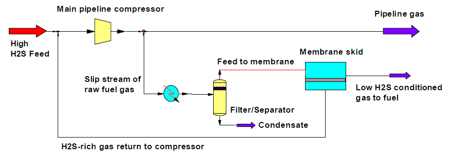
Figure 6 – Process scheme for H2S removal from NG to reach the inlet feedstock quality targets for engines or gas turbines[13].
Also UOP has developed and applied a polymeric membrane for the removal of H2S, testing it in a pilot plant and thus demonstrating the membrane stability at a wide operating conditions range and the proper values of permeability and selectivity.
4.Membrane application for N2 removal
Selective membranes are proposed also for NG denitrogenation but, according to the DOE[14], the challenge of developing competitive membrane for N2/CH4 separation is not yet overcome.Both glassy polymers (nitrogen-permeable) or rubbery polymers (methane-permeable) membranes can be applied. But, while a nitrogen/methane selectivity of 15 at least is required to make the denitrogenation membrane economically competitive, the highest selectivity available with current polymers is only about 2-3. Therefore, strong R&D efforts are required.Some interesting studies can be found in the scientific literature, as the works published by the University of Massachusetts[15] and the Aachen University[16].Currently, MTR and CB&I are the only manufacturers of membranes for nitrogen removal. The membrane module they developed, called NitroSepTM, have been applied for up to 20 MMSCFD NG plants and nitrogen composition up to 15%[17] (refer to Figure 7).
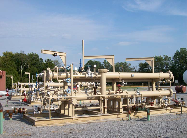
Figure 7 – NitroSepTM module application in California[18].