Gasification Process
Author: Andrea Milioni – Chemical Engineer – On Contract Cooperator – University UCBM – Rome (Italy)
1. Theme description
The gasification process is the thermochemical conversion of a carbonaceous solid or liquid to a gas in presence of a gasifying agent: air, oxygen or steam. Compared to this definition, the combustion process could be associated as a gasification one, however, by definition, gasification requires that oxygen supply is lower than the amount required for complete combustion to carbon dioxide and water (the stoichiometric amount). In these conditions, the reaction products are not only carbon dioxide and water but consist of a combustible gas mixture with a given heating value which depends on three variables: feed elemental composition, inlet gas composition (air, oxygen or steam) and gasifier typology. Furthermore the process produces a solid carbonaceous phase (CHAR), condensable vapors (TAR) and ashes.
The gasification can be carried out directly by adding oxygen (or air) and by exploiting the exothermicity of the reactions to provide the energy necessary for the process or by pyrolysis, supplying heat from outside in the complete absence of oxygen. The gaseous products, essentially hydrogen, carbon monoxide, methane and carbon dioxide, may be used for several purposes such as heating, electricity generation and production of chemicals and fuels.
The gasification process, has been developed on an industrial scale during the 19th century to produce town gas for lighting and cooking. Later, the natural gas and electricity replaced it for these applications, and it was used only for the production of some synthetic chemicals. Since the ’70s, following the crisis of fossil fuels, the realization of dependence on foreign oil have led to the revaluation of the gasification process, in particular the biomass gasification, driven also by the interest in the reduction of greenhouse gas emissions and in the local availability of renewable energy sources.
2. Foundamentals
The gasification process can be divided into 4 basic steps (sketched in Figure 1) that occur within a suitable reactor: heating/drying, pyrolysis, gas-solids reactions and gas phase reactions [1]. When the reactor design ensures high-speed heat transfer and the feed is introduced as small particles, the whole process takes place in short time (about one second) [2].
Heating and drying: in this first step the temperature reaches about 300°C and the feed is completely dried. The greater the moisture amount, the higher the energy needed for drying, with a lower produced gases enthalpy. For this reason, a naturally dry (or previously dried) biomass is desirable. During the heating there is a typical heat transfer phenomenon, with a temperature profile decreasing towards the particle centre: the greater the radius, the longer the time required for the treatment.
Pyrolysis: in this second step, a rapid thermal anoxic degradation of the carbonaceous material takes place. The ideal temperature for this purpose is between 400 and 500°C.
Released products:
Gases: H2, CO, CH4, CO2 and some other light hydrocarbons.
Vapors: The exposition to high temperatures lead to a thermal cracking process generating light and condensable compounds (TAR, Topping Atmospheric Residue) consisting essentially in polyaromatic hydrocarbons.
Solids: residual porous called CHAR consisting in a carbon residue and inorganic compounds (ash).
Gas-Solid Reactions: reactions occurring between CHAR and the added gasifying agent (oxygen, steam, or both). Exothermic reactions, with negative , help to provide energy for the endothermic processes such as drying and pyrolysis.
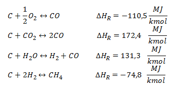
Gas-phase Reactions: there are two main gas-phase reactions, respectively, water gas shift and methanation, for the synthetic natural gas production.
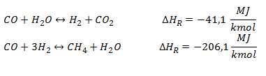
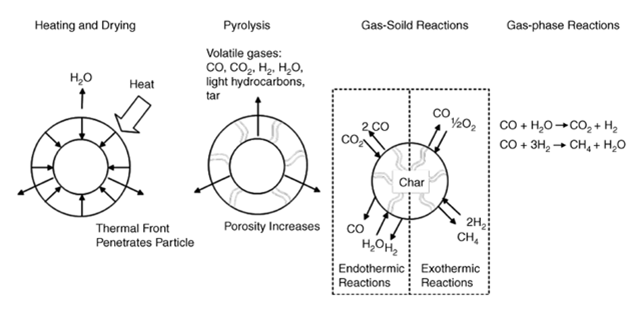
Figure 1 – The Process of Thermal Gasification [3]
3. Gasifiers Typology
Depending on the modality of contact between the gasifying agent and the charge, four reactor types can be identified:
- Fixed Bed;
- Fluidized Bed;
- Entrained Flow;
- Indirect.
The Fixed Bed Gasifiers represent the most consolidated technology thanks to their constructional simplicity, although some difficulties to maintain a uniform temperature along the reactor may arise. These latter involve a series of problems due both to the control system and the quality of the produced syngas. The fixed bed gasifiers are generally used for small-medium size plants (no more than 10-15 tons/hours of biomass). The scaling up to higher potential is very complex because of the impossibility of having a uniform temperature distribution in great size beds.
Depending on the point of product gas intake, different geometries can be classified:
- Updraft (counter-current);
- Downdraft (co-current);
- Crossdraft (cross-current).
The main fixed-bed gasification technologies are known as Lurgi process [4], British Gas Lurgi (BGL) process [5], Wellman-Galusha (WG) process [6] and 100 Ruhr process [7].

Figure 2 – Fixed Bed Gasifiers: Updraft Gasifier (a), Cross Draft Gasifier (b), Down Draft Gasifier (c) [8]
The Fluidized Bed Gasifiers use, together with the feed, an inert material as sand or dolomite. It promotes the mixing, the kinetics and the heat exchange between the biomass particles improving the gasifier efficiency. A periodic sand replacement is required mostly in presence of biomass as fuels, in order to avoid the risks of bed agglomeration. The fluidizing agent, usually air also containing steam, is generally added in various steps. Primary air is fed to the bottom of the bed in order to achieve the minimum fluidization velocity of the solid material, also visible in the formation of bubbles in the sand. In fact the beds operating in close proximity to the minimum fluidization velocity are denominated Bubbling Fluidized Bed (BFB).
When the air velocity is increased above these values, there is a particles entrainment, which makes necessary the installation of a cyclone for the reintroduction of the solid particles inside the reactor. This configuration is called Circulating Fluidized Bed (CFB)[9].
In air(or oxygen)-fed fluidized bed reactors, the syngas methane content is relatively low because the reactor operates as an high temperature autothermal reformer.
Figure 3 – Bubbling Fluidized Bed Gasifier (a) and Circulating Fluidized Bed Gasifier (b) [10]
The Entrained Flow Gasifiers accept gaseous, pulverized or slurry feeds. The fuel is fed inside burners in co-current with oxygen and eventually steam. In case of biomass as feed, this must be pulverized or submitted to a preliminary pyrolysis step. The gasification process takes place at temperatures about 1200°C and pressures above 20 bar. These operating conditions lead to a non-leachable molten slag and a very low TAR content syngas production with consequent simplification of the downstream purifying operations. The high operating pressure results in the production of a compressed syngas that can be used directly in synthesis reactions. The high temperature makes necessary an heat recovery from the gases through the coupling with steam and electricity production, in this way it is reached an important improvement in the process efficiency.
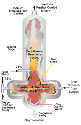
Figure 4 – Entrained Flow Gasifier [11]
In the Indirect Gasifiers, gasification occurs in absence of oxygen therefore without feed combustion. For this reason, the heat required by endothermic reactions must be supplied from outside with steam as gasifying agent. In this configuration, the additional heat can obtained by exploiting an external source or by burning a part of the feed in a separated combustion chamber. The necessary heat amount can be supplied in different ways:
- Direct transfer to the gasification environment;
- Increase of the steam quantity or degree of overheating;
Both the equilibrium thermodynamic laws and experimental data prove that, using steam as gasifying agent rather than air or oxygen at temperatures in the range of 800-900°C, the methane content grows significantly.
4. Environmental and economical benefits of gasification
The great and obvious potential of gasification process is mainly linked to the use of syngas for the production of chemicals such as methanol and fertilizers. Additionally, in some cases the gasification can have the same purpose (i.g. heat and electricity generation) and the same feed typology of incineration process with benefits mainly related to environmental and economic aspects. The gasification of solid fuels normally used for power production (coal, MSW etc.) allows a considerable pollutants reduction such as SOx, NOx and Hg as well as CO2, which is a major cause of global warming. As regards the CO2, some studies have been performed to compare the gasification-based power plant emission with a combustion-based subcritical pulverized coal plant [12]. The obtained results show how the use of gasification slightly reduces the CO2toEnergy-ratio (745 g/KWh against 770 g/KWh) but an important advantage lies in an easier CO2 capture, being more concentrated in the exhaust gas. On the other hand the gasification allows an easier sulphur and nitrogen removal. In fact, while with the combustion there is the formation of SOx end NOx which are relatively difficult to remove, gasification produces different substances: the 93-96% of the sulphur is transformed into H2S and the remaining in COS [13], while nitrogen forms N2 and NH3 that is removed during syngas cleaning. The H2S can be removed by absorption producing elemental sulphur as a valuable by-product, saleable to fertilizers companies. Furthermore, inside the gasifiers dioxins and furans formation is unflavoured and it is possible a significant particular matter reduction with proper treatment. Unlike ash produced with the incineration process, with gasification the slag can be used in roads bed construction.
Table 1 shows how gasification process approaches natural gas emissions.
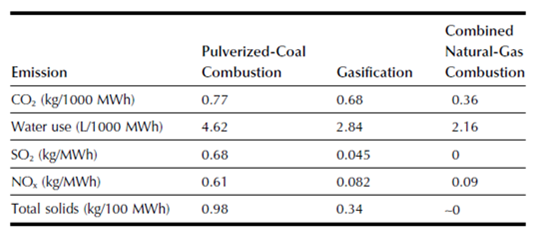
Table 1 – A comparison of emissions from electricity-generation technologies [14]
5. Gasification industry
The Gasification Technologies Council has been realized some important researches to analyse the gasification plants industrial development, which are summarised in graphs available at: www.gasification.org.
Some of them are listed below (Figure 6, 7, 8). By looking at the global market, the gasification in Asia/Australia exceeds the amount related to the other continents put together due to the important growth of chemical, fertilizer and coal to liquids industries in Asia (Figure 6). On the other hand, the countries with large natural gas reserves invest less in this technology. For example in Russia gasification plants are not currently present, while China represents the most relevant investor in this field with the highest number of gasification plants (Figure 7). In conclusion, Figure 8 shows clearly that coal represents the present as well the future of gasifier feedstock.
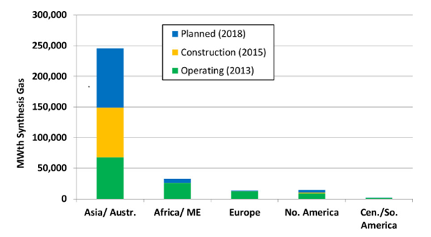
Figure 5 – Gasification capacity by geographic region
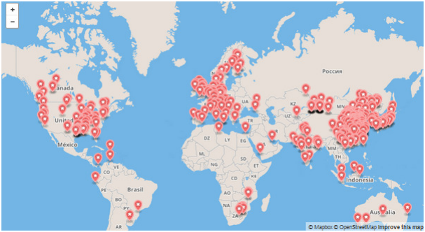
Figure 6 – Map of Gasification Facilities
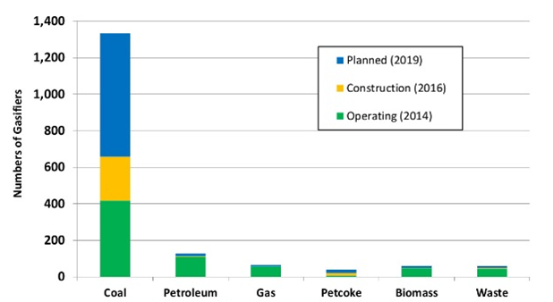
Figure 7 – Number of gasifiers primary feedstock