Dimethyl Ether (DME) Production
Author: Marcello De Falco , Associate Professor, University UCBM – Rome (Italy)
1.Theme description
DME (Dimethyl Ether) is an organic compound mainly used as aerosol propellant and as a reagent for the production of widely applied compounds as the dimethyl sulfate (a methylating agent) and the acetic acid[1].
Recently, companies as Topsoe, Mitsubishi Co. and Total focus their effort to promote DME as a new and sustainable synthetic fuel that can substitute the liquefied petroleum gas (LPG) or blended in fuel mixture thank to its excellent combustion properties (cetane number = 55-60). DME has the potentiality to be fed into diesel engine, which would be only slightly modified, and its combustion prevents soot formation[2],[3].
Also the DME conversion to hydrocarbons is a relevant emerging market[4]. The processes usually known the general terms “Methanol-to-Hydrocarbons” (MTH), Methanol-to-Olefins” (MTO), Methanol-to-Propylene” (MTP), Methanol-to-Gasoline” (MTG) and Methanol-to-Aromatics” (MTA) are more effective if the starting reagent is DME instead of methanol.
For all these reasons, a projected value of DME market equal to 9.7 bln USD by 2020 is foreseen, with a yearly growth of 19.65% between 2015 and 2020[5].
DME is usually produced directly from syngas (CO/H2 mixtures with a eventual amount of CO2, typically below 3%) or by dehydration of methanol, which in turn is produced by syngas. Syngas can be generated from fossil fuels (coal, methane) or renewable sources as biomass or renewable electricity. Moreover, there is a growing interest on direct DME production from CO2-rich mixture.
In the following, an overview of DME production processes applied worldwide is reported and, then, the major production plants actually operative are described.
2.Production Processes
2.1 Direct and Indirect production process
In industrial applications, the DME is produced from the syngas by means of two different configurations[6]:
- one-step process;
- two-steps process.
In the one-step process (direct production process), DME is produced directly from the syngas in one single reactor where a bifunctional catalyst supports both the methanol formation and the methanol dehydration according to the following reactions scheme[7]:
Methanol formation: CO + 2H2 ↔ CH3OH DHo = – 90.4 kJ/mol
Water-gas shift: CO + H2O ↔ CO2 + H2 DHo = – 41.0 kJ/mol
Methanol dehydration: 2CH3OH ↔ CH3OCH3 + H2O DHo = -23.0 kJ/mol
Overall reaction: 3CO + 3H2 ↔ CH3OCH3 + CO2 DHo = -258.3 kJ/mol
The syngas is produced by means of a natural gas steam reforming or coal/petroleum residues gasification and, after the DME synthesis reactor, a purification unit, able to separate the DME from water and methanol in a double distillation stage is needed. The following figure shows a diagram of the one-step process.

In the two steps (indirect) process, the methanol formation from syngas and the DME production from methanol are supported in two separated reactors, where the specific catalysts (copper-based for the first, silica-alumina for the second) are packed. The figure illustrates the block diagram of this architecture.

2.2 DME production from renewable energies
The reactants of the DME synthesis process can be produced from renewable energy as biomass, solar and wind. By this way, the DME is a sort of liquid energy vector, able to store the renewable energy in a easily dispensable, easy applicable and high-energy density fuel.
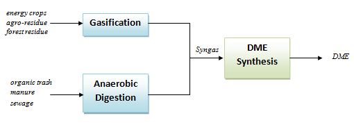
Starting from biomasses as energy crops, agro-residue, forest residue, etc., a gasification process can be applied to generate a syngas stream to be fed to one-step or two-steps DME synthesis process[8]. On the other hand, if the starting biomass is an organic trash, manure or sewage, an anaerobic digestion + pyrolysis system can be applied to generate the CO and H2 stream[9].
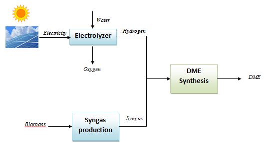
The hydrogen stream in the syngas mixture can be generated by an electrolyzer supplied by electricity produced from renewable power plants as photovoltaics and wind farms and then mixed with CO/CO2. By this way, the renewable energy is “stored” in the DME, which, being a liquid fuel, can be easily distributed, stored and used, differently from the hydrogen itself which has a series of unsolved issues related to the distribution and storage. The following scheme shows a conceptual layout of the DME production from solar/biomass energy.
2.3 DME production as a CO2 valorization process
Instead of the syngas, a CO2-rich feedstock can be supplied to the DME production process, thus converting the CO2 in a high added value product. By this process, the CO2, which is the main GreenHouse gas (GHG), is not emitted but is converted into a fuel which can be burned releasing again the carbon dioxide[10],[11],[12].
Such a configuration is less developed than the conventional syngas-fuelled process, but many research efforts are devoted to improve its performance since it would allow both the production of DME and the reduction of GHG emissions, thus reducing the carbon footprint of DME synthesis.
CO2 presence in the reactor environment leads to two main issues:
- CO2-rich feedstock influences the active state of the catalyst for methanol synthesis, reducing the rate of formation of methanol[13];
- CO2 promotes the reverse Water Gas shift reaction, thus producing H2O and inhibiting the methanol dehydration.
The research is focused mainly on the development of new catalyst, tailored for CO2-rich mixture conversion, and of selective membranes able to remove water from the reaction environment, promoting the methanol dehydration reaction and the DME production[14],[15].
3.Operative plants and new frontiers
The one-step and two-steps DME production processes are relatively well established, with a number of companies proposing the one-step (Topsoe, JFE Ho., Korea Gas Co., Air products, NKK) or two-steps (Toyo, MGC, Lurgi, Udhe) architecture[16].
Among the many applications for DME industrial production, the most interesting are listed below:
- TOYO company has developed a indirect DME production catalyst and technology, fabricating a DME synthesis plant able to be installed in methanol production plant. The high performance MRF-Z® reactor[17], which has the features of multi-stage indirect cooling and a radial flow to the methanol synthesis unit, has a capacity up to 6,000 ton/day in a single train.
- The MegaDME process is a combination of Lurgi MegaMethanol (capacity > 5000 tons/d)[18] and a Dehydration Plant.
- China is the world leader of DME production and use. Currently, there are various DME to Olefins and DME to Propylene facilities in China, while many other projects are advancing toward completion. Fourteen to fifteen facilities are expected to be operational by 2016. Most of them are based on the double-function catalyst developed by the Dalian Institute of Chemical Physics (DICP) for the one-step process[19].
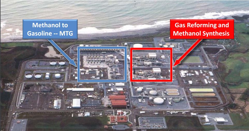
- Methanol-to-Gasoline (MTG) is also an emerging demand segment. Today, six plants use the ExxonMobil’s MTG two-steps technology, with DME as intermediate[20]. In the figure below, the New Zealand SynFuel MTG plant is shown.
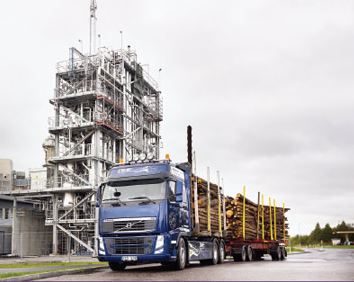
- In Piteå (Sweden), a bio-DME demonstration plant is located. It started the operation in 2010 and it is based on the black liquor (a high-energy residual product of chemical paper and pulp manufacture) gasification process, able to produce a high-quality syngas which then is fed to a DME synthesis unit. The DME produced is, therefore, derived from a renewable energy source (refer to the following figure[21]).
- Fuel DME Production Co, a company of Mitsubishi Gas Chemical, has fabricated a DME production plant in Niigata Factory (Japan), with a capacity of 240 tons/day and which is fed by a methanol stream transported by pipelines (refer to figure [22]).
The new research studies on the DME production process are mainly based on:
- the testing and validation of more efficient catalyst for one-step process[23];
- new reactor configurations as slurry reactors[24] and membrane reactors[25];
- efficient distillation processes as dividing-wall column (DWC) technology and reactive distillation (RD) for DME purification[26].


