Author: Andrea Milioni, Chemical Engineer – On Contract Cooperator – University UCBM – Rome (Italy)
1. Theme description
Scientific progress in the last two centuries has allowed a great development of industrial production activities, modifying the relationship between mankind and the environment. In particular, the exploitation of natural resources has led to changes in the environment, often irreversibly. This raises the need to develop, in parallel to the new technologies, research aimed on the one hand at preventing potential ecological disasters, the other at remedying in case of contamination. In this frame, great are the efforts by developed countries to stimulate applied research for the rehabilitation of polluted sites.
One of the industrial sectors with the largest impact on the environment relates to the Oil and Gas industry. Pollution is due to several activities, including drilling, stimulation and the separation and dehydration operations. Two couples of categories can be individuated in the first place: pollution from punctual of diffuse sources and from chronic or accidental release of pollutants. From the pollutant point of view, this can be either organic or inorganic with, consequently, different environmental fates and repercussion on air, soil and groundwater [1].
The main categories of chemical standards for developing soil remediation guidelines are represented by: inorganic parameters, metals, hydrocarbons, halogenated aliphatics, pesticides, other organics and radionuclides. Both before and after the remediation is necessary to perform some important procedures. The first concerns monitoring and planning methods of remediation, where chemical, hydrogeological and microbiological analysis are made to characterize the soil and the pollution typology. The individuation of standards depends both on human and ecological features (as the use of land and water) as well as the kind of the contaminated matrix (physic-chemical characteristics)[2]. The second concerns the methods effectiveness control: the treatment is complete when the remedial target levels have been achieved for the specified use of the soils and the risk to the ecosystem is minimized. The number of samples to collect should be adequate to provide a statistically reliable result and strictly depends on the use of the soils and the possible contaminants migration. During the decontamination procedure, any possible impact on the related matrixes (such as air in case of VOC emission) should be constantly monitored [3]. The Soil Screening Guidance [4] is an EPA tool for the standardization of the step-by-step evaluation and clean-up of contaminated soils destined to possible residential use of land. In the following, main techniques for soil remediation will be presented focusing on the cleaning up after hydrocarbon contamination.
2. Remediation methods
The goal of remediation is to remove, or to make harmless, substances contaminating the soil or groundwater. The remediation processes can be applied directly to the site of contamination, in situ, or after removing the contaminated soil, ex situ. Among the latter, there are the treatments on site, when working on the excavation site or off site, when you need to transport in plants located elsewhere. It is possible a classification of the different processes in accordance with the mechanism for cleaning up: non-organic (chemical, physical or thermal) or biological. The choice of different types of treatment is linked to several factors related to the nature of the pollutant, the polluted site, the type of technology (basically to its efficiency and cost). Briefly, the main techniques of both non-biological and biological remediation will be described below.
3. Non-biological Remediation
Soil Washing
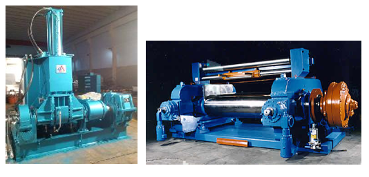
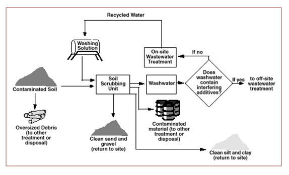
Description: this technique, generally carried out on site, consists in the soil decontamination by washing with water and possible addition of other substances (chelating agents, surfactants, acids or bases), according to the needs, in order to improve the ‘solid-liquid extraction in contact with the ground. The latter undergoes an initial pre-treatment to remove coarse material and then switch to the washing stage where there is the process of extraction-solubilisation of the pollutant, which passes into the aqueous solution. Subsequently it has a solid-liquid separation that provides the clean solid and starts the water to the treatment thanks to which the pollutant is separated, concentrated, and recirculates the process water for the next wash. The capacity of reclamation is quite high (about 25 t / h). The duration of treatment Soil Washing is usually short, from one to three months and increases as the percentage of clay and silt content in the soil.
Development and applicability: currently, it is developed on a large scale and found more applications in Europe than in America especially in the removal of heavy metals. It can be applied, however, to a wide range of pollutants, including hydrocarbons and pesticides.
Critical issues: May be limited by silty and clayey soils that make it more difficult to solid-liquid separation. Physical separation is generally not effective for treating the chemically adsorbed metals [5].

Figure 1 – Soil Washing [6]
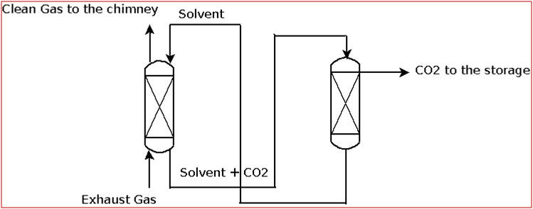
Solvent Extraction
Description: technique operating on site using a solvent to improve the efficiency of extraction, in a process very similar to that previously described. Since traces of solvent may remain in the ground at the end of the treatment, a criterion for its choice concerns the degree of toxicity.
Development and applicability: the solvent extraction has proven effective in removing a wide range of organic pollutants, from hydrocarbons to organochlorine pesticides, VOCs and petroleum wastes. The plants in full scale come to treat 20 t / h of soil.
Critical issues: It is not applicable for the removal of inorganic pollutants and some processes are limited by the solid matrix moisture content and fine particles. The presence of detergents and emulsifiers can unfavourably influence the extraction performance [7].
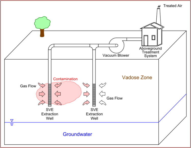
Soil Vapor Extraction (SVE)
Description: this technique, also called Soil Vacuum Extraction, is applied in situ and used in the reclamation of the unsaturated zone of the soil, the area in which the pores of the soil contain air or water at a pressure lower than the atmospheric one (by capillarity). Using a system of wells, vacuum is applied so as to induce a controlled flow of air from outside which brings with it the volatile compounds and some semivolatiles. This system comprises a gas treatment extracts made from activated carbon filters, systems of incineration or cold traps; the treated gas is released into the atmosphere or re-injected into the ground.
Development and applicability: This method finds application mainly in soils at medium depth and permeability to avoid the short-circuiting of the steam flow or a difficulty in its circulation. The pollutants to be removed must have a vapor pressure greater than 1 mm Hg at 20°C. Both SVE and air sparging are used to clean up several acres of contaminated soil and groundwater at the Vienna PCE Superfund site in West Virginia [8].
Critical issues: Soils with moisture content above 50%, tend to adsorb the pollutant compounds, compromising the effectiveness of the technology.

Figure 2 – Soil Vapor Extraction (SVE) System for Vadose Zone Remediation Air sparging
Air Sparging
Description: technology operating in situ in which air is bubbled through a contaminated aquifer. The air bubbles cause stripping of volatile organic compounds present in the saturated zone, the part of the subsurface in which the pores of the soil are filled with water at pressure equal to or greater than the atmospheric one. In general, the exit gas from the underground are conveyed by means of a suction system, which often coincides with a SVE inserted into the unsaturated zone.
Development and applicability: it finds ideal application in homogeneous soils with high permeability and unconfined aquifers, polluted by volatile compounds, halogenated and hydrocarbons.
Critical issues: if it is not used in conjunction with SVE, an unwanted migration of pollutants outside the contaminated area may occur. Special attention should be given in the event of large doses of pollutant supernatants (eg. Hydrocarbons in suspension), to prevent the push and the bubbling cause aerosols in the surrounding areas.

Figure 3 – Combined Air Sparging and Soil Vapor Extraction system
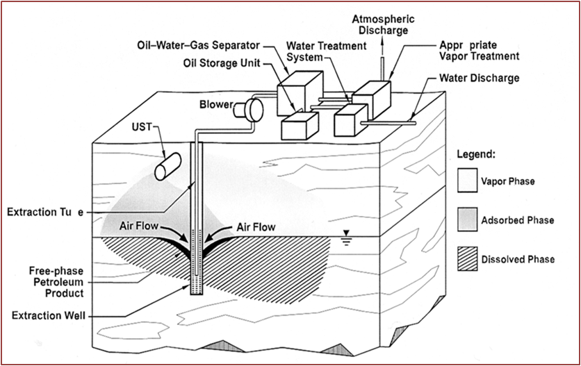
Dual Phase Extraction
Description: this technology allows the in situ simultaneous removal of the contaminants present in the unsaturated zone and the saturated zone of the soil (In case the contamination concerns both stages) by the means of a vacuum pump. In this way extends the applicability of the SVE to the saturated zone of the soil. Downstream of the vacuum pump it is necessary to separate the liquid from the vapour phase and proceed to the train of treatments for the different phases.
Development and applicability: suitable for this technology are the low permeability soils, usually clay, in which the cone of depression extends in depth, going to increase the thickness of the unsaturated zone. An important factor to consider concerns the hydrogeology of the site, crucial to understand the degree of applicability and effectiveness of this treatment.
Critical issues: The technique is not recommended in case of deep contamination of the aquifer and in the case where the contamination is very extensive.

Figure 4 – Typical Dual Phase Extraction Scheme [11]
Solidification / Stabilization
Description: in the solidification processes, the pollutants are physically linked, or trapped in a solid matrix, while in the stabilization, chemical reactions transforming the pollutant in a less mobile species, are favoured. An example is given by the cement that immobilizes many metal contaminants by forming insoluble hydroxides, carbonates and silicates (stabilization) as well as providing an encapsulating matrix for the leaching attenuation (solidification) [12].
Development and applicability: this technique is used mainly for the treatment of inorganic pollutants, including radionuclides, while the presence of organic material may constitute an obstacle for the success of the neutralizing process.
Critical issues: increase in volume of the final product (up to twice the volume to be treated) and long-term stability of the material inertization.
Thermal Desorption
Description: This ex-situ treatment consists in the desorption of volatile pollutants through the supply of heat from outside. The material polluted, is sent to a rotary kiln or to a heated auger system, where, by increasing the temperature the formation of gases and vapours of polluting compounds is guaranteed. The contaminants destruction is realised using a secondary treatment units [13].
Development and applicability: there are two processes in response to operating temperature, low (90-320°C) and high (320-560°C). In the first case, generally suitable for non-halogenated hydrocarbons, no thermal oxidation occurs and the physical characteristics of the soil remain unchanged. In the second case, instead, semivolatile organic compounds, volatile metals and polycyclic aromatic compounds are removed by operating, often in combination with the incineration processes, solidification/stabilization and dechlorination [14].
Critical issues: the economy of the process is affected by the moisture content of the material to be reclaimed.
Incineration
Description: technology that works off site used for the final disposal of contaminated materials resulting from the treatment of soil washing, solvent extraction and thermal desorption. The contaminated material is fed into a burner where takes place the volatilization and oxidation of organic compounds at temperatures between 870°C and 1200°C, in the presence of oxygen. Often it is necessary to supply the burner with an auxiliary fuel, both to trigger and to maintain the combustion.
Development and applicability: used especially if contamination concerns explosives, chlorinated hydrocarbons, polychlorinated biphenyls and dioxins. In the presence of heavy metals, it is necessary to inert ashes.
Critical issues: at the exit of the burner, gas treatment, particulate abatement and neutralization of acids (HCl, NOx and SOx) systems are needed.
4. Biologic Remediation
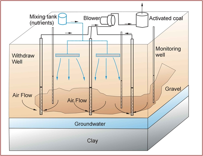
Bioventing
Description: technology operating in situ, for the soils treatment in the unsaturated zone. It stimulates the degrading action of microorganisms already present in the soil (native microbial flora), providing oxygen and, where necessary, mineral nutrients into the ground by percolation or by direct input with specific spargers. Oxygen is normally provided through direct input or air suction through spears stuck in the ground.
Development and applicability: it is useful in the remediation of hydrocarbons contaminated soils and is adaptable to soils with high permeability. Process often coupled with SVE: first making an SVE with the removal of the more volatile hydrocarbons, then performs a bioventing, simply by reducing the air flow and injecting nutrients for degrading residual non-volatile hydrocarbon components.
Critical issues: avoid the application when soils are: too heterogeneous, so contaminated by pollutants to create a saturated zone and in areas close to aquifers.

Figure 5 – Typical Bioventing system
Biosparging
Description: technology similar to bioventing, which operates in situ for the treatment of saturated soils and groundwater. The acceleration of the native microbial flora degradation is done through direct air and appropriate nutrients entering the contaminated area.
Development and applicability: it is normally used to degrade the contaminants that are dissolved in the groundwater, adsorbed on soil particles below the groundwater level or in the capillary fringe area. Effective is the application in petroleum products reduction, usually realised for underground storage tank sites [16].
Critical issues: the presence of an hydrocarbons concentration such as to decrease the permeability or to be toxic, can make ineffective the action of biosparging.
Natural attenuation
Description: in this way is performed an intrinsic bioremediation, exploiting the nature ability to restore a polluted environment. Set up a site for a natural attenuation essentially means: run a targeted monitoring to know the precise boundary between the contaminated area and the clean zone, a campaign of analysis for the measurement of some basic parameters (temperature, pH, redox potential, concentration nitrate, nitrite and ammonia, phosphates) and enumeration of bacterial populations specific for the different types of biodegradation.
Critical issues: the presence of non-biodegradable pollutants, existence of contamination phenomena able to convey hazardous substances towards targets of environmental interest and need to complete the remediation in a short time.
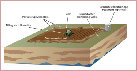
Landfarming
Description: technique operating on site which consists of arranging the contaminated material on a non-permeable surface in a layer normally less than one meter, ensuring, during the decontamination period, the maintenance of the best conditions for the microbial populations development. It is essential to ensure, from the beginning of the treatment, a correct balance of the main nutritional components of the system: carbon, nitrogen and phosphorus, in relations respectively 100: 5: 1 in addition to the content of water content (60-70% of the saturation value), and the soil pH, which must be neutral. Furthermore it is necessary to facilitate the air entry for the correct oxygen supply to the bacterial populations, generally by mixing the soil to be treated or by entering bulking agents (wood chips, expanded silicon, etc.). This process requires an extended time frame, possibly up to 24 months, depending on a number of factors, including the nature of the contamination, the concentrations of contaminants, types of soil and volume of soil to be remediated. Landfarming to remove volatile constituents from soils through evaporation, without biological degradation, is not acceptable, unless are realised the volatile constituents capture and treatments [17].
Critical issues: the presence of volatile pollutants that threaten the operators health, unavailability of adequate land area.

Figure 6 – Typical Landfarming operation
Biopiles
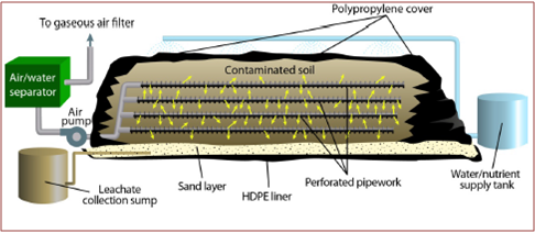
Description: technique very similar to landfarming, with the main difference residing in the method of oxygen transfer. In the preparation of the biopile soil layers are superimposed with interspersed perforated tubes, used to distribute, air and solutions containing the necessary nutrients [19]. In the presence of volatile pollutants, the biopile can be covered with waterproof sheets with appropriate openings to let out the steam to be sent to treatment. The presence of the sheets also facilitates the monitoring of the parameters indicated in the landfarming section.
Development and applicability: The application of biopiles has been guaranteed by numerous studies that have shown good removal efficiencies especially for total petroleum hydrocarbon (THP) [20].

Figure 7 – Typical Biopiles Scheme
Bioslurry
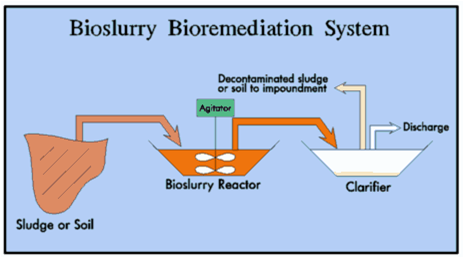
Description: technique consisting in the remediation of soil within fermentation reactors. Inside the reactors can be controlled effectively operating parameters or use non-native bacterial populations (bioaugmentation). Theoretically it would be possible to use genetically modified bacteria, practice today banned in open field [22].
Development and applicability: to date, this method has been applied only to remove substances not readily degradable.
Critical issues: high costs and reduced volumes of treated soils limit the operational capabilities of bioslurry.

Figure 8 – Bioslurry system
Microbiological Barriers
Description: A system for the in situ treatment of groundwater. Inside the aquifer is placed transversally a barrier consisting of soil or suitable solid support colonized by microorganisms. Therefore the barrier is “passive”, and biodegradation occurs by contact between the water that runs through it and microorganisms adhering to it. It is also necessary to construct a series of wells for the air and nutrients intake for the present microorganisms.
Development: the microbiological barriers, have had a good spread in Italy with some application examples [24].
Emerging Technologies
In recent years, research in the field of bioremediation is evolving to try to increase the contamination cases resolved by biological remediation. In this regard two research lines are being developed to exploit synergistic actions respectively between microorganisms and plants (bioremediation/phytoremediation) and between bacteria and fungi [25]. Not to be overlooked are the research of genetics to modify microorganisms and make them capable of degrading substance considered recalcitrant and the research to make possible actions in situ even in situations where it is very difficult to convey sufficient amount of oxygen. Have particular importance the cases of hydrogen or magnesium peroxides use [26].
In the non-bio field, permeable reactive barriers (continuous and non), characterized by high conductive reactive media capturing the contaminants by deviating the natural flows, are producing invigorated research results [27]. Another interesting field of research can be individuated in the use of hydraulic fracture technology for soil and groundwater remediation. FRx promotes the Hydraulic fractures as an optimal in situ treatment for the removal of materials from extraction wells. They utilizes US EPA practices and individuates four key factors distinguishing the uses of hydraulic fractures for soil and groundwater remediation from those ideated for the oil and gas production: volume, depth pressure and chemical additives [28].
__________________________
[1] www.saveballona.org/gasoilfields/Oil&gaspollution.pdf
[3] G.J. Graening 2007, Remediation Journal, 17(4), Wiley
[5] G. Dermont et al. 2008, Journal Of Hazardous Materials, 152, 1-31, Elsevier
[7] http://www.frtr.gov/matrix2/section4/4-15.html
[8] https://clu-in.org/download/Citizens/a_citizens_guide_to_soil_vapor_extraction_and_air_sparging.pdf
[9] “Conceptual Diagram of Basic Soil Vapor Extraction (SVE) System for Vadose Zone Remediation” by Gwremed
[10] Hinchee (1994), Airsparging for Site Remediation, Lewis Publishers
[12] http://clu-in.org/techfocus/default.focus/sec/Solidification/cat/Overview/
[13] http://www.midwest soil.com/thermal-desorption/
[14] http://www.frtr.gov
[15] http://pixshark.com/bioventing.htm
[16] http://www.epa.gov/oust/cat/biosparg.htm
[17] SA EPA 2005
[18] US EPA 1994
[19] US EPA 2011
[20] Kao et al. 2009, World Environmental ad Water Resources Congress, pp. 1-10.
[21] http://www.tankonyvtar.hu/hu/tartalom/tamop425/0032_kornyezettechnologia_en/ch02s02.html
[22] UK EA 2002
[23] http://www.alken-murray.com/bioslurry.html
[24] Buzzelli et al. (1997), In Situ and On Site Bioremediation, Vol.1, pp. 423-428, Battelle Press
[25] http://ergobalance.blogspot.it/2013/11/applications-of-bioremediation-and.html
[26] http://www.h2o2.com/remediation/in-situ-soil-and-groundwater-treatment.aspx?pid=91&name=In-situ-Soil-and- Groundwater-Treatment, A.Goi et al. 2011, Chemosphere 82, pp. 1196-1201, Elsevier


